Max 10 Plus • FPGA-014

As multimedia gradually becomes one of the most salient aspects of today’s computing, Terasic’s MAX 10 Plus is designed to accelerate your development of new multimedia technologies, such as audio video content analysis and recognition, media streaming, computer vision, image processing, etc.

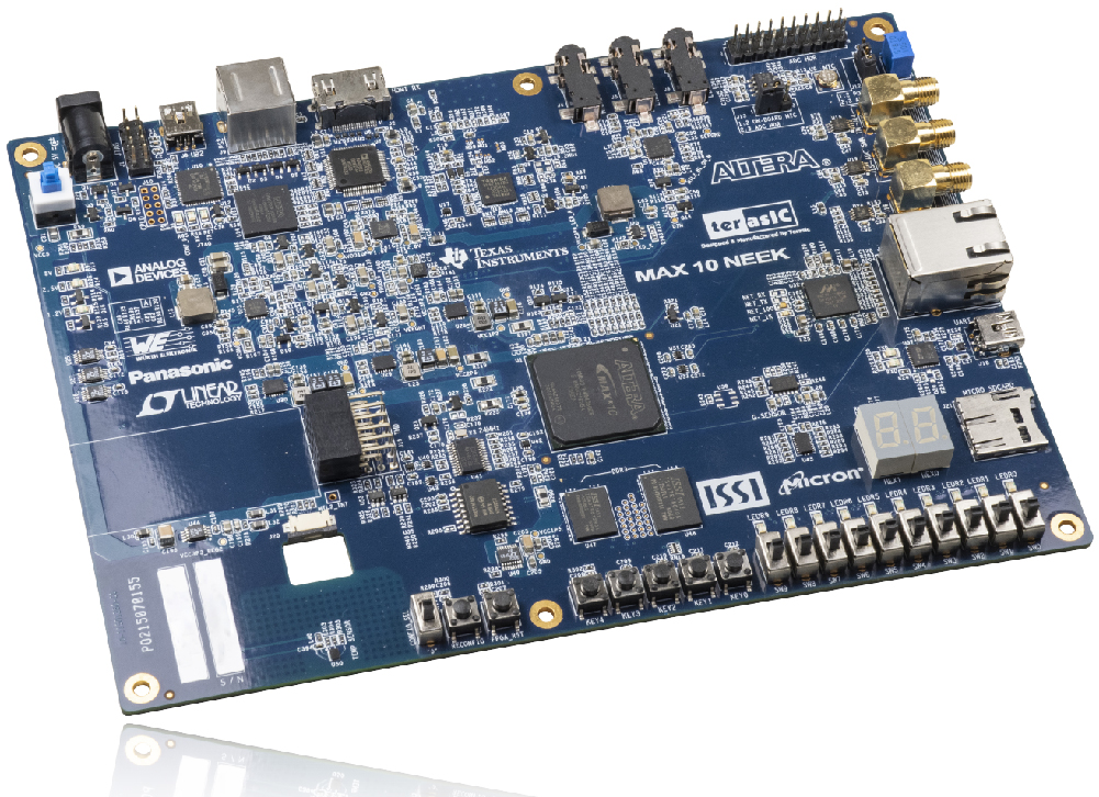
The kit features high-bandwidth memory (DDR3), high-speed communication interface (Gigabit Ethernet), various multimedia interfaces (HDMI Receiver / AUDIO codec), useful sensors (temperature and Light sensor/ Accelerometer/ Power monitor) make up this rich feature set, along with a variety of interfaces connecting the MAX 10 Plus to the outside for Internet of Things (IoT) applications across markets.

Built with a comprehensive design environment, the kit allows developers to rapidly customize their processor and IP to suit their specific requirement, instead of limiting the software around the predetermined feature set of the processor. The all-in-one embedded solution provided by MAX 10 Plus allows developers to make the best use of the parallel nature of FPGAs.

SKU: fpga-014 Categories: , Tags: ,

Description

FPGA Device

  • MAX 10 10M50DAF484C6G Device
  • Integrated dual ADCs, each ADC supports 1 dedicated analog input and 8 dual function pins
  • 50K programmable logic elements
  • 1,638 Kbit M9K Memory
  • 5,888 Kbits user flash memory
  • 144 18 × 18 Multiplier
  • 4 PLLs
  • Programming and Configuration
  • On-board USB Blaster
  • Optional JTAG direct via 10-pin header
  • One slide switch for dual boot image selection

Memory Devices

  • 64Mx16 1 Gb DDR3 SDRAM
  • 128Mx8 1 Gb DDR3 SDRAM
  • 512Mb quad serial peripheral interface (quad SPI) flash memory
  • Micro SD card socket
  • Communication and Expansion
  • Gigabit Ethernet PHY with RJ45 connector
  • UART to USB
  • PS/2 mouse/keyboard connector
  • 2×6 TMD Expansion Header

Audio

  • 24-bit CD-quality audio CODEC with mic-in, line-in, line-out jacks

Video Input

  • HDMI video input

Analog

  • Two MAX 10 FPGA ADC SMA inputs
  • Potentiometer input to ADC
  • On-Board MIC input to ADC
  • 2×10 Header for MAX 10 FPGA ADC inputs
  • One DAC output

Sensors

  • Humidity and temperature sensor
  • Light sensor
  • Accelerometer
  • Power monitor

Clocking for users

  • One 10 MHz single-ended, external oscillator clock source
  • Three 50 MHz single-ended, external oscillator clock source

Switches, Buttons and LEDs

  • Five push-buttons
  • Ten slide switches
  • Ten red user LEDs
  • Two 7-segment displays

Power

  • 5V/3A DC input
Scroll to Top